Drawings
Piping & Instrument Drawings – P & ID’s
P&IDs are usually designed to present functional information about a system or component.
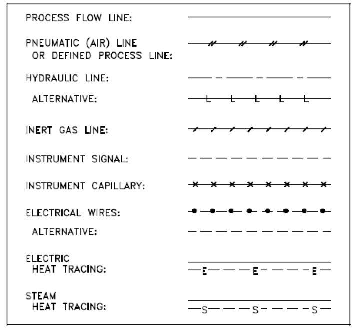
Examples are piping layout, flowpaths, pumps, valves, instruments, signal modifiers, and controllers
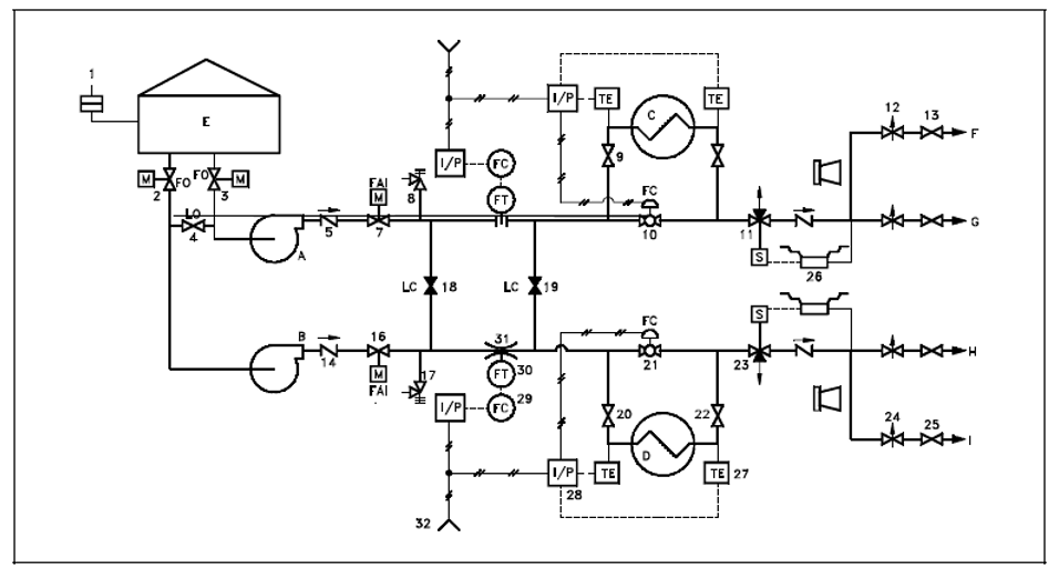
As a rule P&IDs do not have a drawing scale and present only the relationship or sequence between components. Just because two pieces of equipment are drawn next to each other does not indicate that in the plant the equipment is even in the same building; it is just the next part or piece of the system. These drawings only present information on how a system functions, not the actual physical relationships.
Because P&IDs provide the most concise format for how a system should function, they are used extensively in the operation, repair, and modification of the plant.